
@elmaya , great thing, but I'm not sure it will work in a serial connection. I want to measure the voltage on such a board through a dedicated P1 connector :
https://easyeda.com/editor#id=fdceba4bd ... 3e62bd4a04,
Ground is not common and if I connect it according to this diagram I will have a short circuit. Would you have any idea how to solve this?
Or, for example, measure subsequent voltage values on batteries by differences between the values between the cell voltages.
From the P1 socket the GND contact to GND Wemos and then:
1. B1 at socket contact 2 - we have B1 voltage
2. B2 at socket contact 3, B2 = B2-B1 - we have B2 voltage
3. B3 = B3-B2-B1- we have voltage B3
4. B4 = B4-B3-B2-B1- we have the voltage B4
5. B5 = B5-B4-B3-B2-B1- we have voltage B5
6. B6 = B6-B5-B4-B3-B2-B1- we have voltage B6
7. B7 (on the contact 8 - 24V) = B7-B6-B5-B4-B3-B2-B1 - we have the voltage B7
woltomierz 6 wejść na arduino mega
-
piomar2
- Posts: 369
- Joined: Fri Apr 26, 2019 5:32 pm
- Location: Bukowice
-
elmaya
- Posts: 1485
- Joined: Wed Jun 27, 2018 5:48 pm
- Location: El Saucejo - Sevilla
I will see it as soon as I have some free time. 
-
piomar2
- Posts: 369
- Joined: Fri Apr 26, 2019 5:32 pm
- Location: Bukowice
I tested 3 wemos and I selected 3 resistors for the divider. A colleague of Lech_ needs a layout (diagram above). I would do it without a problem on arduino mega but my friend is more suited (it's obvious) Your solution on wemos. Unfortunately, this is not a measurement of several points by weight. The measurement must be made on cells connected in series. I see no other solution than measuring in subsequent points and subtracting the previous ones:
We measure the voltage between mass and:
1. B1 at socket contact 2 - we have B1 voltage
2. B2 at socket contact 3, B2 = B2-B1 - we have B2 voltage
3. B3 = B3-B2-B1- we have voltage B3
4. B4 = B4-B3-B2-B1- we have the voltage B4
5. B5 = B5-B4-B3-B2-B1- we have voltage B5
6. B6 = B6-B5-B4-B3-B2-B1- we have voltage B6
7. B7 (on the contact 8 - 24V) = B7-B6-B5-B4-B3-B2-B1 - we have the voltage B7
and another measurement cycle from the beginning (B1)
With such a selected divider, the max voltage at B7 measurement will be about 24V (2.4 V on the A0 input of the wemosa) and may be higher when the 18650 cells are fully charged (7x4.3V = 30.1V). Then the divider will be 3.1V (safe for wemos).
Considering the solution in arduino mega, 7 A0-A6 inputs should be used, and 74HC4051 from An1 to An7
The use of identical voltage dividers at the inputs is convenient.
I treat it entertaining, because I doubt that the solution will interest someone else. What do you think about it?
We measure the voltage between mass and:
1. B1 at socket contact 2 - we have B1 voltage
2. B2 at socket contact 3, B2 = B2-B1 - we have B2 voltage
3. B3 = B3-B2-B1- we have voltage B3
4. B4 = B4-B3-B2-B1- we have the voltage B4
5. B5 = B5-B4-B3-B2-B1- we have voltage B5
6. B6 = B6-B5-B4-B3-B2-B1- we have voltage B6
7. B7 (on the contact 8 - 24V) = B7-B6-B5-B4-B3-B2-B1 - we have the voltage B7
and another measurement cycle from the beginning (B1)
With such a selected divider, the max voltage at B7 measurement will be about 24V (2.4 V on the A0 input of the wemosa) and may be higher when the 18650 cells are fully charged (7x4.3V = 30.1V). Then the divider will be 3.1V (safe for wemos).
Considering the solution in arduino mega, 7 A0-A6 inputs should be used, and 74HC4051 from An1 to An7
The use of identical voltage dividers at the inputs is convenient.
I treat it entertaining, because I doubt that the solution will interest someone else. What do you think about it?
-
elmaya
- Posts: 1485
- Joined: Wed Jun 27, 2018 5:48 pm
- Location: El Saucejo - Sevilla
What is being used to balance the batteries?
-
piomar2
- Posts: 369
- Joined: Fri Apr 26, 2019 5:32 pm
- Location: Bukowice
I have no idea. Lechu_ has this knowledge - he needs a solution ...
-
Lechu_
- Posts: 219
- Joined: Tue Oct 11, 2016 5:41 pm
- Has thanked: 1 time
I'm going to build a powerwall from 18650 cells in size 7S. All for charging with the Volt SINUSPRO-2000S solar inverter. its maximum charging voltage is up to 29V, so don't worry, the maximum voltage on the cell is around 4.14V. The whole is connected in parallel in a 10-size powerwall and ultimately 20 PCBs with 18650 batteries. The system will also get BMS but later. Directly, the voltage on the cells will be possible to suspect with such a clever system:
https://www.youtube.com/watch?v=MmEe8cR_4Qg
Preview of voltage by connecting an IDC tape. And here additionally using the fact that these PCBs have IDC connectors with which we can measure the voltage values of individual cells (in the powerwall of the voltage group on the entire floor of the "single cell") I came up with the idea to make this preview remote via the Internet. I really want to build 4 or 5 towers of 10 PCBs and have a remote view for each. Mainly to check if one of the groups has low or too high voltages and thus you may need to replace some batteries 18650.
https://www.youtube.com/watch?v=MmEe8cR_4Qg
Preview of voltage by connecting an IDC tape. And here additionally using the fact that these PCBs have IDC connectors with which we can measure the voltage values of individual cells (in the powerwall of the voltage group on the entire floor of the "single cell") I came up with the idea to make this preview remote via the Internet. I really want to build 4 or 5 towers of 10 PCBs and have a remote view for each. Mainly to check if one of the groups has low or too high voltages and thus you may need to replace some batteries 18650.
-
elmaya
- Posts: 1485
- Joined: Wed Jun 27, 2018 5:48 pm
- Location: El Saucejo - Sevilla
I think it would be better to use for example BQ76930 to balance, protect and read the voltages of the batteries controlled from esp8266 through I2C
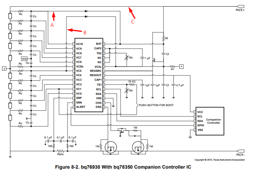
It would be a much more effective design.
It would be a much more effective design.
-
Lechu_
- Posts: 219
- Joined: Tue Oct 11, 2016 5:41 pm
- Has thanked: 1 time
I found something interesting:
https://easyeda.com/grahamob/arduino-bms-bq76930-copy
I just want to view online tension, BMS will be in addition, but maybe this project above will be interesting to develop?
https://easyeda.com/grahamob/arduino-bms-bq76930-copy
I just want to view online tension, BMS will be in addition, but maybe this project above will be interesting to develop?
-
elmaya
- Posts: 1485
- Joined: Wed Jun 27, 2018 5:48 pm
- Location: El Saucejo - Sevilla
There are many examples and the communication protocol is there.
for example this.
https://github.com/nseidle/BMS
for example this.
https://github.com/nseidle/BMS